Mfr Part # 5768
ADAFRUIT RP2040 PROP-MAKER FEATH
Adafruit Industries LLC
License: See Original Project 3D Printing Light Solder / Desoldering Third Hand / Vises Adafruit Feather
Guide by Ruiz Brothers and Liz Clark
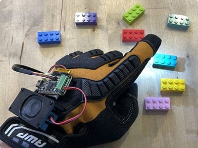
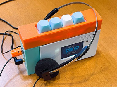
Build a fun and playful 3D printed MP3 player with CircuitPython and an RP2040 PropMaker Feather! It's a boombox for young makers, but with a twist: use a color sensor to detect a LEGO DUPLO brick and play a song, sound effect, or audio clip. Each colored brick plays a different audio file.
You can use the Adalogger FeatherWing microSD card slot to add extra media storage to add as many MP3 audio files as you can store!
All of the electronics are housed in a 3D printed enclosure that features a storage bin for holding several DUPLO bricks. It features a 3W 4Ohm mono speaker that connects to the I2S audio amplifier that's built-into the RP2040 PropMaker Feather.
Pop a DUPLO brick into the boombox and click the rotary knob to have it say what color the brick is. You can turn the knob to turn up or down the volume. The on-board NeoPixel LED will light up to the corresponding brick color.
This project is configured to detect 11 different colors from the DUPLO brick box. You can add new colors by reading the values from the sensor and assigning a new MP3 file in the code. The code page in this guide will cover how it all works.
Music featured in this project is by written by Dan Q for Adafruit. Check out all of Dan Q's music on the Adafruit Soundcloud page.
Adalogger FeatherWing - RTC + SD Add-on For All Feather Boards
FeatherWing Doubler - Prototyping Add-on For All Feather Boards
1 x STEMMA QT Cable
1 x STEMMA QT Cable
1 x microSD card
1 x Slide Switch
The project is designed to be compatible with 2x2 DUPLO bricks. The brick box set is a great beginner's kit featuring several bricks featuring different colors.
The following fasteners are required to assemble this project.
12x M2.5 x 6mm steel machines crews
6x M3 x 4mm steel machine screws
10x M3 x 6mm steel machine screws
4x M3 x 8mm steel machine screws
4x M3 steel hex nuts
2x M5 x 8mm steel machine screws
2x M5 steel hex nuts
The diagram below provides a general visual reference for wiring of the components once you get to the Assembly page. This diagram was created using the software package Fritzing.
Adafruit uses the Adafruit Fritzing parts library to create circuit diagrams for projects. You can download the library or just grab individual parts. Get the library and parts from GitHub - Adafruit Fritzing Parts.
The PropMaker Feather RP2040 and Adalogger FeatherWing are fitted onto a FeatherWing Doubler.
The AS7341 color sensor is connected to the PropMaker Feather RP2040 via STEMMA QT cable.
The Rotary Encoder is connected to the color sensor via STEMMA QT Cable.
The speaker is connected to the speaker output pins on the PropMaker Feather RP2040 screw block terminals.
The slide switch is connected to the EN (enable) and GND (ground) pins on the FeatherWing Doubler.
The PropMaker Feather RP2040 is powered by a 3x AA battery back.
CircuitPython is a derivative of MicroPython designed to simplify experimentation and education on low-cost microcontrollers. It makes it easier than ever to get prototyping by requiring no upfront desktop software downloads. Simply copy and edit files on the CIRCUITPY drive to iterate.
Follow this step-by-step to quickly get CircuitPython running on your board.
Download the latest version of CircuitPython for this board via circuitpython.org
Click the link above to download the latest CircuitPython UF2 file.
Save it wherever is convenient for you.
To enter the bootloader, hold down the BOOT/BOOTSEL button (highlighted in red above), and while continuing to hold it (don't let go!), press and release the reset button (highlighted in red or blue above). Continue to hold the BOOT/BOOTSEL button until the RPI-RP2 drive appears!
If the drive does not appear, release all the buttons, and then repeat the process above.
You can also start with your board unplugged from USB, press and hold the BOOTSEL button (highlighted in red above), continue to hold it while plugging it into USB, and wait for the drive to appear before releasing the button.
A lot of people end up using charge-only USB cables and it is very frustrating! Make sure you have a USB cable you know is good for data sync.
You will see a new disk drive appear called RPI-RP2.
Drag the adafruit_circuitpython_etc.uf2 file to RPI-RP2.
The RPI-RP2 drive will disappear, and a new disk drive called CIRCUITPY will appear.
That's it, you're done! :)
You want to edit your code.py or modify the files on your CIRCUITPY drive but find that you can't. Perhaps your board has gotten into a state where CIRCUITPY is read-only. You may have turned off the CIRCUITPY drive altogether. Whatever the reason, safe mode can help.
Safe mode in CircuitPython does not run any user code on startup and disables auto-reload. This means a few things. First, safe mode bypasses any code in boot.py (where you can set CIRCUITPY read-only or turn it off completely). Second, it does not run the code in code.py. And finally, it does not automatically soft-reload when data is written to the CIRCUITPY drive.
Therefore, whatever you may have done to put your board in a non-interactive state, safe mode gives you the opportunity to correct it without losing all of the data on the CIRCUITPY drive.
To enter safe mode when using CircuitPython, plug in your board or hit reset (highlighted in red above). Immediately after the board starts up or resets, it waits 1000ms. On some boards, the onboard status LED (highlighted in green above) will blink yellow during that time. If you press reset during that 1000ms, the board will start up in safe mode. It can be difficult to react to the yellow LED, so you may want to think of it simply as a slow double click of the reset button. (Remember, a fast double click of reset enters the bootloader.)
If you successfully enter safe mode on CircuitPython, the LED will intermittently blink yellow three times.
If you connect to the serial console, you'll find the following message.
Auto-reload is off.
Running in safe mode! Not running saved code.

CircuitPython is in safe mode because you pressed the reset button during boot. Press again to exit safe mode.

Press any key to enter the REPL. Use CTRL-D to reload.
You can now edit the contents of the CIRCUITPY drive. Remember, your code will not run until you press the reset button, or unplug and plug in your board, to get out of safe mode.
If your board ever gets into a really weird state and CIRCUITPY doesn't show up as a disk drive after installing CircuitPython, try loading this 'nuke' UF2 to RPI-RP2. which will do a 'deep clean' on your Flash Memory. You will lose all the files on the board, but at least you'll be able to revive it! After loading this UF2, follow the steps above to re-install CircuitPython.
Download flash erasing "nuke" UF2
Once you've finished setting up your Feather Prop Maker with CircuitPython, you can access the code, MP3 files and necessary libraries by downloading the Project Bundle.
To do this, click on the Download Project Bundle button in the window below. It will download to your computer as a zipped folder.
# SPDX-FileCopyrightText: 2026 Liz Clark for Adafruit Industries
# SPDX-License-Identifier: MIT

"""Duplo Color Boombox"""

import board
import sdcardio
import storage
import audiobusio
import audiomixer
import audiomp3
from digitalio import DigitalInOut, Direction
from adafruit_as7341 import AS7341
from adafruit_seesaw import digitalio, neopixel, rotaryio, seesaw

#Power Setup
external_power = DigitalInOut(board.EXTERNAL_POWER)
external_power.direction = Direction.OUTPUT
external_power.value = True

#SD Card setup

spi = board.SPI()
cs = board.D10
sdcard = sdcardio.SDCard(spi, cs)
vfs = storage.VfsFat(sdcard)
storage.mount(vfs, "/sd")

#Audio
try:
    mp3 = audiomp3.MP3Decoder(open("/sd/blue.mp3", "rb"))
except OSError as error:
    print(f"{error} - did you put the mp3 files on the micro SD card?")

i2s = audiobusio.I2SOut(board.I2S_BIT_CLOCK, board.I2S_WORD_SELECT, board.I2S_DATA)
mixer = audiomixer.Mixer(voice_count=1, sample_rate=mp3.sample_rate, channel_count=1,
                         bits_per_sample=mp3.bits_per_sample)
i2s.play(mixer)
mixer.voice[0].level = 0.5

#Color Sensor
i2c = board.STEMMA_I2C()
sensor = AS7341(i2c)
sensor.led_current = 4  # increments in units of 4
sensor.led = False

brick_dictionary = [
    {'song': "/sd/blue.mp3", 'value': (1619, 13852, 19215, 18562, 12912, 8818, 9512, 5440),
     'color': ((0, 255, 255))},
    {'song': "/sd/orange.mp3", 'value': (2517, 3983, 5661, 6864, 16857, 39049, 55151, 35696),
     'color': ((255, 60, 0))},
    {'song': "/sd/coral.mp3", 'value': (3004, 6712, 7499, 7160, 13858, 46007, 65535, 39278),
     'color': ((250, 50, 50))},
    {'song': "/sd/purple.mp3", 'value': (2562, 20704, 19222, 15806, 16624, 18399, 27316, 22525),
     'color': ((125, 0, 255))},
    {'song': "/sd/red.mp3", 'value': (1453, 2629, 4050, 4656, 5527, 13403, 31096, 21368),
     'color': ((255, 0, 0))},
    {'song': "/sd/yellow.mp3", 'value': (3051, 4446, 8633, 17412, 37450, 48224, 56249, 34726),
     'color': ((255, 150, 0))},
    {'song': "/sd/butter.mp3", 'value': (4102, 8631, 13692, 29000, 58147, 63230, 65535, 43143),
     'color': ((255, 255, 0))},
    {'song': "/sd/green.mp3", 'value': (1383, 2767, 5850, 12964, 22118, 16304, 12669, 7008),
     'color': ((120, 255, 0))},
    {'song': "/sd/lime.mp3", 'value': (3017, 8109, 17948, 36761, 48754, 38009, 31671, 19457),
     'color': ((150, 255, 0))},
    {'song': "/sd/lightblue.mp3", 'value': (4188, 29507, 42326, 53214, 54067, 37512, 34129, 23544),
     'color':((100, 250, 255))},
    {'song': "/sd/white.mp3", 'value': (5246, 27506, 33883, 44702, 62766, 64254, 65535, 48334),
     'color':((255, 255, 255))},
    ]

def find_closest_brick(reading, dictionary, max_distance=50000):
    """
    Find the brick with the closest matching sensor values.

    Args:
        new_reading: Tuple of 8 sensor values
        brick_dictionary: List of brick dictionaries
        max_distance: Maximum distance to consider a valid match

    Returns:
        Tuple of (matched_brick, distance) or (None, distance) if no good match
    """
    best_match = None
    best_distance = float('inf')

    for brick in dictionary:
        # Calculate total distance (sum of absolute differences)
        distance = sum(abs(v1 - v2) for v1, v2 in zip(reading, brick['value']))

        if distance < best_distance:
            best_distance = distance
            best_match = brick

    # Only return a match if it's close enough
    if best_distance > max_distance:
        return None

    return best_match

#Rotary STEMMA I2C
seesaw = seesaw.Seesaw(i2c, 0x36)
encoder = rotaryio.IncrementalEncoder(seesaw)
seesaw.pin_mode(24, seesaw.INPUT_PULLUP)
switch = digitalio.DigitalIO(seesaw, 24)
switch_state = False

pixel = neopixel.NeoPixel(seesaw, 6, 1)
pixel.brightness = 1
pixel.fill((0, 0, 0))

last_position = -1
volume = 0.5 # volume
play = False
play_state = False

mp3 = audiomp3.MP3Decoder(open("/sd/boot.mp3", "rb"))
mixer.voice[0].play(mp3, loop=False)

while True:

    # make clockwise rotation positive
    position = -encoder.position

    if position != last_position:
        if position > last_position:
            #decrease volume
            volume = volume - 0.05
            volume = max(volume, 0)
        else:
            #increase volume
            volume = volume + 0.05
            volume = min(volume, 1)
        # set the audio volume
        mixer.voice[0].level = volume
        print(volume)
        last_position = position

    if not switch.value and not switch_state:
        print("Button pressed")
        switch_state = True
        if not play:
            sensor.led = True
            sensor_color = sensor.all_channels
            matched_brick = find_closest_brick(sensor_color, brick_dictionary)
            print(sensor_color)
            if matched_brick is not None:
                print(matched_brick['song'])
                mp3 = audiomp3.MP3Decoder(open(matched_brick['song'], "rb"))
                pixel.fill(matched_brick['color'])
                play = True
                mixer.voice[0].play(mp3, loop=False)
                play_state = True
            else:
                print("insert brick")
                mp3 = audiomp3.MP3Decoder(open("/sd/uhoh.mp3", "rb"))
                mixer.voice[0].play(mp3, loop=False)
        else:
            if play_state:
                i2s.pause()
                play_state = False
            else:
                i2s.resume()
                play_state = True

    if switch.value and switch_state:
        sensor.led = False
        switch_state = False
        print("Button released")

    if not mixer.playing:
        play_state = False
        play = False
        pixel.fill((0,0,0))
After downloading the Project Bundle, plug your Feather Prop Maker into the computer's USB port with a known good USB data+power cable. You should see a new flash drive appear in the computer's File Explorer or Finder (depending on your operating system) called CIRCUITPY. Unzip the folder and copy the following items to the Feather Prop Maker's CIRCUITPY drive.
lib folder
code.py
Your Feather Prop Maker CIRCUITPY drive should look like this after copying the lib folder and code.py file:
Mount the microSD card (FAT formatted) to your computer and add the MP3 audio files from the /mp3_files_for_sd_card folder from the Project Bundle to the root directly of the storage device. After adding the MP3s to the microSD card, remove it from the computer and pop it into the microSD card slot on the Adalogger FeatherWing.
Make sure the MP3s are added to the microSD card and NOT the SD folder in the CIRCUITPY drive.
At the top of the code, the EXTERNAL_POWER pin is enabled to power up the peripherals on the Feather.
#Power Setup
external_power = DigitalInOut(board.EXTERNAL_POWER)
external_power.direction = Direction.OUTPUT
external_power.value = True
The SD card is set up using sdcardio and is mounted to the /sd mount point. The mount point is set to readonly within CircuitPython so that it can be read/write on your OS when the CircuitPython drive is mounted. This means that you can drag and drop audio files to the SD card over USB.
#SD Card setup

spi = board.SPI()
cs = board.D10
sdcard = sdcardio.SDCard(spi, cs)
vfs = storage.VfsFat(sdcard)
storage.mount(vfs, "/sd")
Next is the audio setup. For this project, MP3 audio files are used. The MP3 decoder and built-in I2S output are passed to a Mixer object. This lets you control the volume via software.
#Audio
mp3 = audiomp3.MP3Decoder(open("/sd/blue.mp3", "rb"))

i2s = audiobusio.I2SOut(board.I2S_BIT_CLOCK, board.I2S_WORD_SELECT, board.I2S_DATA)
mixer = audiomixer.Mixer(voice_count=1, sample_rate=mp3.sample_rate, channel_count=1,
                         bits_per_sample=mp3.bits_per_sample)
i2s.play(mixer)
mixer.voice[0].level = 0.5The color sensor is instantiated over I2C and its white LED is turned off by default.
#Color Sensor
i2c = board.STEMMA_I2C()
sensor = AS7341(i2c)
sensor.led_current = 4  # increments in units of 4
sensor.led = False
A dictionary is used to hold each Duplo brick's MP3 audio file name, color reading and NeoPixel color. You can add or edit entries to the dictionary for additional bricks or to change up the associated MP3.
brick_dictionary = [
    {'song': "/sd/blue.mp3", 'value': (1619, 13852, 19215, 18562, 12912, 8818, 9512, 5440),
     'color': ((0, 255, 255))},
    {'song': "/sd/orange.mp3", 'value': (2517, 3983, 5661, 6864, 16857, 39049, 55151, 35696),
     'color': ((255, 60, 0))},
    {'song': "/sd/coral.mp3", 'value': (3004, 6712, 7499, 7160, 13858, 46007, 65535, 39278),
     'color': ((250, 50, 50))},
    {'song': "/sd/purple.mp3", 'value': (2562, 20704, 19222, 15806, 16624, 18399, 27316, 22525),
     'color': ((125, 0, 255))},
    {'song': "/sd/red.mp3", 'value': (1453, 2629, 4050, 4656, 5527, 13403, 31096, 21368),
     'color': ((255, 0, 0))},
    {'song': "/sd/yellow.mp3", 'value': (3051, 4446, 8633, 17412, 37450, 48224, 56249, 34726),
     'color': ((255, 150, 0))},
    {'song': "/sd/butter.mp3", 'value': (4102, 8631, 13692, 29000, 58147, 63230, 65535, 43143),
     'color': ((255, 255, 0))},
    {'song': "/sd/green.mp3", 'value': (1383, 2767, 5850, 12964, 22118, 16304, 12669, 7008),
     'color': ((120, 255, 0))},
    {'song': "/sd/lime.mp3", 'value': (3017, 8109, 17948, 36761, 48754, 38009, 31671, 19457),
     'color': ((150, 255, 0))},
    {'song': "/sd/lightblue.mp3", 'value': (4188, 29507, 42326, 53214, 54067, 37512, 34129, 23544),
     'color':((100, 250, 255))},
    {'song': "/sd/white.mp3", 'value': (5246, 27506, 33883, 44702, 62766, 64254, 65535, 48334),
     'color':((255, 255, 255))},
    ]
A function called find_closest_brick() is used to determine if the Duplo brick that is held up to the color sensor matches one of the defined colors in the dictionary. Since the color readings are analog and can vary depending on external light, the function returns the closest match to the current reading. If there isn't a close enough match, it returns None. You can change the sensitivity by adjusting the max_distance value.
def find_closest_brick(reading, dictionary, max_distance=50000):
    """
    Find the brick with the closest matching sensor values.

    Args:
        new_reading: Tuple of 8 sensor values
        brick_dictionary: List of brick dictionaries
        max_distance: Maximum distance to consider a valid match

    Returns:
        Tuple of (matched_brick, distance) or (None, distance) if no good match
    """
    best_match = None
    best_distance = float('inf')

    for brick in dictionary:
        # Calculate total distance (sum of absolute differences)
        distance = sum(abs(v1 - v2) for v1, v2 in zip(reading, brick['value']))

        if distance < best_distance:
            best_distance = distance
            best_match = brick

    # Only return a match if it's close enough
    if best_distance > max_distance:
        return None

return best_matchThe seesaw rotary encoder is next. The built-in switch is used in the code, along with the NeoPixel.
#Rotary STEMMA I2C
seesaw = seesaw.Seesaw(i2c, 0x36)
encoder = rotaryio.IncrementalEncoder(seesaw)
seesaw.pin_mode(24, seesaw.INPUT_PULLUP)
switch = digitalio.DigitalIO(seesaw, 24)
switch_state = False

pixel = neopixel.NeoPixel(seesaw, 6, 1)
pixel.brightness = 1
pixel.fill((0, 0, 0))
There are a few variables and states that are used in the loop:
last_position - tracks the last position of the rotary encoder
volume - volume for the audio output through the Mixer object
play - state to track if a song has started playing
play_state - state to track if a song is actually playing or is paused\
Right before the loop, the boot.mp3 file is played through the speaker.
last_position = -1
volume = 0.5 # volume
play = False
play_state = False

mp3 = audiomp3.MP3Decoder(open("/sd/boot.mp3", "rb"))
mixer.voice[0].play(mp3, loop=False)In the loop, the rotary encoder position is monitored. If the position increases, the volume increases. If it decreases, the volume decreases.
while True:

    # make clockwise rotation positive
    position = -encoder.position

    if position != last_position:
        if position > last_position:
            #decrease volume
            volume = volume - 0.05
            volume = max(volume, 0)
        else:
            #increase volume
            volume = volume + 0.05
            volume = min(volume, 1)
        # set the audio volume
        mixer.voice[0].level = volume
        print(volume)
        last_position = position
Pressing the rotary encoder button initiates the color sensor to get a reading. The sensor LED turns on, gets a reading on all channels and passes the reading to the find_closest_brick() function. If the code finds a match, then it starts playing the associated MP3 file and lights up the NeoPixel with the associated color.
If a song is currently playing and the button is pressed, then the button toggles play/pause.
When the mixer is no longer playing the song, it resets play and play_state to False and turns off the NeoPixel.
if not switch.value and not switch_state:
        print("Button pressed")
        switch_state = True
        if not play:
            sensor.led = True
            sensor_color = sensor.all_channels
            matched_brick = find_closest_brick(sensor_color, brick_dictionary)
            print(sensor_color)
            if matched_brick is not None:
                print(matched_brick['song'])
                mp3 = audiomp3.MP3Decoder(open(matched_brick['song'], "rb"))
                pixel.fill(matched_brick['color'])
                play = True
                mixer.voice[0].play(mp3, loop=False)
                play_state = True
            else:
                print("insert brick")
                mp3 = audiomp3.MP3Decoder(open("/sd/uhoh.mp3", "rb"))
                mixer.voice[0].play(mp3, loop=False)
        else:
            if play_state:
                i2s.pause()
                play_state = False
            else:
                i2s.resume()
                play_state = True
    if switch.value and switch_state:
        sensor.led = False
        switch_state = False
        print("Button released")

    if not mixer.playing:
        play_state = False
        play = False
pixel.fill((0,0,0))Individual 3MF files for 3D printing are oriented and ready to print on FDM machines using PLA filament. Original design source files may be downloaded using the links below.
The Doubler FeatherWing is secured to the back cover using screws.
The back cover snap fits onto the case frame.
The rotary encoder, color sensor and speaker are secured to individual mounting plates which are attached to the front plate using screws.
The front plate is secured to the case framing with more screws.
The storage bin is fitted and sandwiched in between the back cover and case framing.
The handle is secured to the case framing using screws.
The parts require a 3D printer with a minimum build volume of 100 (X) x 70mm (Y) x 158mm (Z).
The duplo knob requires support material. Use your preferred slice settings for supports or reference the settings below.
Support Type: Tree
Branch distance: 5mm
Branch diameter: 6mm
Top interface layer: 2
The project assembly was designed in Fusion 360. Once opened in Fusion 360, It can be exported in different formats like STEP, STL and more.
Electronic components like Adafruit's boards, displays, connectors and more can be downloaded from the Adafruit CAD parts GitHub Repo.
If you need a better explanation for soldering the headers for Feather products, you can review the guide below for tips and tricks.
How To Solder Headers
By Erin St Blaine
Gather up the headers needed for the Feather, Adalogger FeatherWing, and Doubler.
2x 12-pin male headers
2x 16-pin male headers
2x 12-pin female headers
2x 16-pin female headers
Use a breadboard to help keep the headers straight while soldering.
Fit the 12-pin and 16-pin male header pins onto the bottom of the Adalogger FeatherWing PCB.
Solder all of the pins in place. Remove the Feather carefully from the breadboard when finished.
Use a breadboard to help keep the headers straight while soldering.
Fit the 12-pin and 16-pin male header pins onto the bottom of the Feather RP2040 PropMaker PCB.
Solder all of the pins in place. Remove the Feather carefully from the breadboard when finished.
Fit the 12-pin and 16-pin female headers onto the male headers that are soldered on the Feather and FeatherWing.
Then, place the female headers onto the top of the FeatherWing Doubler, making sure the pins are inserted in the correct location.
Keep the pins in place while soldering all of the pins together.
Remove the Feather RP2040 PropMaker and Adalogger FeatherWing from the FeatherWing Doubler.
Make sure all of the headers have sufficient solder and strong joints.
Use a sharp hobby knife to cut the LiPo Charging trace on the back of the PropMaker Feather RP2040. This must be cut to prevent accidental battery calamity with alkaline batteries when USB is plugged in.
Be careful when using a hobby knife to cut the trace to insure you are safe and only the part you want to cut is cut and nothing else.
Use a sharp hobby knife to cut the LED trace on the back of the AS7341 light sensor. This needs to be cut to prevent accidental color sensing light leaking from the green LED.
If you are unsure about your soldering skills, there is an excellent guide to help:
Adafruit Guide To Excellent Soldering
By Bill Earl
Prepare a set of two wires about 3.5inches (9cm) in length.
Using wire strippers, remove a bit of insulation from the tips of each wire.
Tin the exposed wire by applying a bit of solder to them.
This will help prevent the strands of wire from fraying.
Snip off one of the leads on the slide switch, either the far left or right but not the middle. Then trim the two remaining leads short, about half their length.
Be sure to wear eye protection when cutting small bits of metal which may fly in unpredictable directions.
Solder the two wires to each of the leads on the slide switch.
A pair of helping hands can assist while soldering wires in place.
Solder one wire to a ground pin on the Doubler FeatherWing.
Then, solder the remaining wire to the EN (enable) pin.
Double check the wires from the slider have been soldered to the correct pins on the Doubler FeatherWing.
Test the slide switch by connecting the Feather RP2040 PropMaker to the Doubler FeatherWing.
Install 3x AA batteries into the AA battery holder.
Plug in the cable from the AA battery pack. Ensure the built-in switch is on the ON position.
Use the slide switch to power on the Feather.
The Feather on-board NeoPixel LED should light up indicating it is getting power.
Then use the slide switch to power off the Feather.
Use 4x M2.5x 6mm long machine screws to secure the Doubler FeatherWing to the back cover.
Place the Doubler PCB over the four standoffs on the back cover.
Insert and fasten the M2.5 to secure the Doubler FeatherWing to the back cover.
Insert the slide switch into the switch holder at an angle.
Then firmly press the body of the switch so it sets flush with the surfaces of the holder.
Use two M3 x 4mm long machine screws to secure the switch holder to the back cover.
Place the switch holder over the cutout for the switch with the two mounting holes lined up.
Insert and fasten the M3 screws to secure the switch holder to the back cover.
The slide switch actuator should be accessible on the other side of the back cover.
Insert the microSD card into the microSD card slot on the Adalogger FeatherWing.
Install the Adalogger FeatherWing onto the upper section on the Doubler FeatherWing.
Firmly press down to fully seat the PCB.
With the battery connected to the Feather RP2040 PropMaker, fit it onto the remaining section on the Doubler FeatherWing.
Firmly press down to fully seat the PCB.
Place the AA battery holder onto the back cover in between the four walls.
Slide the battery clip over the battery holder so the keyed edge is fitted in between the rails on the back cover.
Ensure the battery clip is fitted correctly and the battery holder is secured to the back cover.
Use four M3 x 8mm long machine screws and hex nuts to secure the speaker to the speaker plate.
Place the speaker plate over the speaker with the mounting holes lined up.
While holding the two in place, insert a machine screw and thread a hex nut to secure them together.
Repeat for all four mounting holes.
Use four M2.5 x 6mm long machine screws to secure the color sensor to the sensor mounting plate.
Place the color sensor over the four standoffs so the mounting holes are lined up.
While holding parts together, insert and fasten the machine screws to secure them together.
Remove the washer and hex nut from the rotary encoder.
Insert the shaft of the rotary encoder through the hole in the rotary mounting plate.
Orient the PCB so the STEMMA QT connectors are lined up with the notches on the wall of the mounting plate.
Insert the washer over the shaft and thread the hex nut.
Firmly tighten the hex nut to secure the rotary encoder to the mounting plate.
Orient the front plate with the case frame.
Insert the front place into the case frame. Firmly press down so the front plate sits flush with the case frame.
Use six M3 x 6mm long machine screws to secure the front plate to the case frame.
Insert and fasten six M3 screws to secure the front plate to the case frame.
Use for M3 x 4mm long machine screws to secure the speaker mounting plate to the front plate.
Place the speaker mounting plate over the speaker standoffs on the front plate.
While holding parts together, insert and fasten the screws to secure the parts together.
Get the two STEMMA QT cables ready to connect to the rotary encoder and color sensor.
Connect the longer STEMMA QT cable to the left side of the color sensor.
Use the shorter STEMMA QT cable to connect the color sensor to the rotary encoder.
Place the color sensor mounting plate over the sensor standoffs on the front plate.
While holding the mounting plate in place, insert and fasten four M2.5 x 6mm long machine screws to secure the sensor mount to the front plate.
Place the rotary mounting plate over the remaining standoffs on the front plate.
While holding the plate in place, insert and fasten four M3 x 6mm long machine screws to secure the rotary mount to the front plate.
Double check all of the mounting plates are sitting flush with the front plate and all of the screws are fully tightened.
Use two M5 x 8mm machine screws and hex nuts to secure the handle to the case frame.
Slide the handle over the case frame so the two mounting holes line up.
While holding parts, insert and fasten the screws to secure the handle to the case.
Insert and thread the M5 hex nuts to the screws.
Ensure the hex nuts are fully seated. Use a pair of vise grips or pliers to fully tighten the hex nuts.
Insert the two-colored wires from the speaker into the speaker pins on the Feather RP2040 PropMaker.
Use a slotted screwdriver to secure the speaker wires to the screw block terminals.
Plug in the longer STEMMA QT cable to the connector on the Feather RP2040 PropMaker.
Double check the cables are secured.
Slide the storage bin into the case frame so the walls are fitted in between the ridges of the storage bin.
Begin fitting the back cover over the case framing, making sure the cables are fitted inside.
Firmly press the back cover onto the case to snap fit them closed.
Orient the rotary knob with the shaft of the rotary encoder.
Line up the flat edges while inserting the knob.
Firmly press the knob to fully seat the parts together.
Test the knob by rotating, ensuring it moves ok.
Use the slide switch to power on the Feather RP2040 PropMaker.
Test the color sensor by inserting a Duplo brick and pressing the rotary encoder knob. The LED should change color to the color of the brick used.
Use the storage bin to hold a few Duplo bricks.
Stacked bricks (5 in total) can be fitted into the storage bin.
Congratulations on your build! The projects code is set to read 11 colors, which are included with the Duplo brick box starter set.
Insert a DUPLO brick into the color sensing area.
Click rotary encoder to play MP3.
The built-in NeoPixel lights up to corresponding brick color.
While playing audio, click the rotary knob to pause/play. Turn rotary knob to increase/decrease the volume.
If no brick is detected, an audible "Uh Oh" sound will be played.