Mfr Part # 3330
LCD LIGHT VALVE
Adafruit Industries LLC
License: See Original Project 3D Printing LCD / TFT Wearables
Courtesy of Adafruit
Guide by Ruiz Brothers
Overview
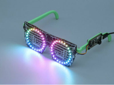
In this guide, we’ll show you how to build pair of electronic sunglasses. These are really cool because you can actually control the dark tint from the glass.
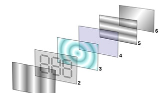
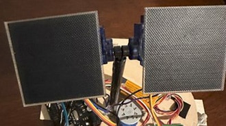
This special panel of glass is a Liquid Crystal Light Valve (a.k.a a LCD Controllable Blackout Panel) and they’re mainly used in welding helmets because it can protecting your eyes from really bright sparks.
Sandwiched in between two sheets of glass is a layer of liquid crystal material. When voltage is applied to the electrodes, it turns dark and filters out bright light. Depending on how much voltage is applied, you can control the tint or opaqueness of the glass.
A Liquid Crystal Light Valve (LCLV) is a device that uses the properties of liquid crystals to control the level of illumination passing through an optical system. It's basically what goes on in your LCD monitor/TV/projector etc., but for each individual pixel.
We recommend walking through the following tutorial to get familiar with the components used in this project.
You'll need the following parts to build this project.
You'll also need the following tools and supplies to complete this project.
You can 3D print the bricks using opaque filament on almost any desktop 3D printer. The 3D printed parts can be downloaded with the link below. If you don’t have a 3D printer, the files are free to download so can send them to a 3D printing service.
The design is modeled in Autodesk Fusion 360 and designed to print in PLA filament. The parts were 3D printed using the BCN3D Sigma.
Download the files from Thingiverse
download from Pinshape
You can easily update the size or add features by editing the Fusion360 designs. The sketches are all listed in the timeline, so it's easy to adjust the size to each component.
Depending on your 3D printer, you may need to adjust the slice settings. We tested the enclosure on a BCN3D
Sigma. The LCD-frame.stl part will require support materials. The parts are oriented to print "as is".
Nozzle: 0.3mm
Extrusion Multiplier: 1.0
Extrusion Width: 0.3mm
Layer Height: 0.2mm
Nozzle Temperature: 225c
Print Speed: 60mm/s
The LCD-bat.stl will require supports to hold the walls for the slide switch, hinge and the curved arm end section.
Make sure to disable "dense supports" and vertical upper and lower separation layers to make the supports easier to remove.
We added multiple pillar resolutions to support sections of the parts while printing. Use one 8mm pillar to hold the hinge section. The slide switch walls are thinner, so we'll need to use a small resolution of 2mm to fit inside. We used 4mm pillars to hold the end of the arm.
To make removal easy, we increased the "horizontal offset" to .7mm.
We can reduce retraction and stress on the extruder and filament while printing supports by connecting the support pillars together. Enable "extra inflation distance" to 1mm to combine all of the pillars into one section.
We'll want the walls of the LCD-bat.stl part to be really strong by making sure gaps between them are solid (no zig zags inside the gaps). We used a .4mm nozzle but had to adjust the nozzle diameter to .3mm with an extrusion width of .3mm to make sure no "zig zag" paths are inside the wall gaps. To enable parameters between walls you'll need to set the overlap to 50%.
Make sure to always preview tools paths by stepping through each layer/line before printing to insure proper tool paths.
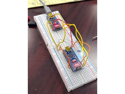
The circuit diagram above shows how the components will be wired together. This won't be 100% exact in the actual circuit but it's a very close approximation.
Positive from LCD to Resistor
Negative from LCD to Resistor
Resistor to female JST connector
Switch to Positive wire of JST
Battery to female JST connector
The circuit will be powered by a 3.7V 100mAh Lithium-ion battery via JST connection. The battery plugs directly into the JST slide switch adapter.
To start this project, we'll begin by attaching the 10K resistor to the female JST connector. The resistor will allow the circuit to drain the voltage from the LCD panel when the switch is set off (so it's necessary if you want to be able to turn the tint on and off!). This resistor will need to be wired across the negative AND positive electrodes on the female JST connector.
To fit the resistor onto the female JST connector we'll need to bend the right-angle pins straight. We used flat pliers to straighten each pin. Now we can bend the pins away from each other, so the resistor has enough space to fit between the two pins.
We'll need to bend the legs from the resistor near the beginning of the body. Use flat pliers to shape both pins like shown in the pictures. We're basically wrapping the legs from the resistor around the two electrodes on the female JST connector. This way, the resistor can stay in place while soldering them together.
Lay the bent resistor pins onto the JST pins and solder the pin together. With both resistor pins soldered to the JST pins we can shorten the resistor pins by trimming off the excess with flush cutters. But leave some metal because we need to attach wires to them.
It doesn't matter which leg of the resistor is soldered to which electrode on the female JST connector. The resistor is not polarized.
Once we're finished, we can set this aside. Moving forward, we'll work on using a second female JST connector for building the slide switch adapter.
It's a good idea to visualize how the components will be wired together. Here, we have the battery, slide switch, female JST connector, and male JST connector. When placed near the 3D printed enclosure arm piece, you can see how they'll fit into the enclosure. Using this visual, you can get an idea for long the wires will actually need to be.
It's important to connect the male JST connector from the battery to the correct wires on the slide switch adapter. So, we'll need to take note of were the positive and negative wires will connect.
Here's how to tell which electrode (or Pin) is positive and negative on the female JST connector. On the top side of the JST connector is a little notch on the edge – This is the positive side. Use this little notch as an indicator for seeing how to correctly wire the female JST connector.
It's support important that the wiring is connected to the correct electrode!
Next, we'll need to cut off a portion from the JST extension cable so that we can attach the male JST connector to the slide switch. Measure the length of the cable so it's about 24mm long. Then, cut the wire (the side with the male JST connector) down to size.
Next up, we’ll need to attach the positive wire from the male JST cable to one of the electrodes on the slide switch. Using wire strippers, remove a small amount of insulation from the tip of the wire to expose it. Then, apply a small amount of solder to the strands of wire to “tin” them. This will make it easier to attach the wire to the metal electrode on the slide switch. Repeat this process for the negative wire.
Grab the slide switch and remove one of the electrodes (either the far left or right, but NOT the middle!) using flush snips. Then, “tin” the two remaining electrodes with a bit of solder.
Now we can work on attaching the positive wire from the male JST cable to one of the electrodes on the slide switch. Before we do any soldering, go ahead and slip on a piece of heat shrink tubing over the wires – This will allow us to insulate the exposed bare metal from the slide switch. Bring the tip of the positive wire close to an electrode on the switch so they're touching. Then use the tip of the soldering iron to heat them together, essentially soldering them together.
Next, we'll need to connect the negative wire from the male JST cable to the negative electrode on the female JST connector. Remember, the positive side of the female JST connector has the notch. Solder the negative wire from the male JST cable to the negative electrode (the side with no notch) on the female JST connector. Be sure to slip on a piece of heat shrink tubing before soldering.
We’ll need to connect the remaining electrode from the slide switch to the positive electrode on the female JST connector. To do this, we’ll need a new piece of wire. This can be from the excess cable we cut from the JST extension cable from earlier. Cut it down to size and then strip and tin the wire. Now we can we solder this wire from the positive electrode on the female JST connector to the remaining electrode on the slide switch.
And now we have a “Slide Switch Adapter”. So why did we make this? We’ll, it’ll make recharging the battery much easier because we can disconnect it from the circuit. We basically avoided having to cut the positive wire from the battery to wire in a slide switch. So, why not use a JST extension cable with a built-in switch? Well, they’re super large compared to the enclosure, so it simply won’t fit. This is the smallest we could get this component, so it’s pretty important to make it as small as possible.
Next, we'll work on attaching wires to the electrodes on the LCD Panel. First, do a "dry fit" and place the LCD glass panel over the 3D printed frame. This will allow us to gauge the lengths of wire necessary for connecting it to the rest of the circuit. Grab the right arm (with built-in enclosure) and fit it into the hinge of the frame on the right side.
Now we can measure out how long the positive and negative wires will need to be. The 3D printed right side arm has the built-in enclosure, so the wires will need to reach it. They're two sets of positive and negative electrodes on the side of the glass panel. The negative wire will connect to the top left electrode, while the positive wire will connect to the electrode on the top right. Because of this, the negative wire will be longer than the positive wire. Cut the wires down to size.
Now we can work on prepping the wires for connecting them to the electrodes on the LCD panel. Use wire strippers to remove a bit of insulation from the tips of each wire. Then, secure the wires to third helping hands so we you tin the tips by applying a small amount of solder.
Next, we'll trim the electrodes on the LCD panel short. Then, tin the two electrode with a small amount of solder. Now we can connect the negative wire to the top left electrode on the LCD panel. Then, connect the positive wire to the top right electrode on the LCD panel.
Now grab the female JST connector (the one with the 10k resistor) and secure it to third helping hands. We'll need to connect the positive and negative wires from the LCD panel to the electrodes on the female JST connector. Remember, the side of the female JST connector with the notch is the positive side!
That's it for the wiring! Now we can work on install the components into the 3D printed parts.
To start the assembly, we'll begin by mounting the LCD panel to the 3D printed frame.
Position the LCD on top of the frame and press fit the panel by applying a small amount of pressure on the two edges (between the electrodes) of the panel. Don't mount it at an angle, lay the panel flat and apply even pressure to both sides.
If the LCD won't fit, make sure you don't have excessive solder on the pins.
Position the negative wire and press fit it into the groove so that it runs across the top of the frame. You can use the back side of tweezers to make it easier.
The slide switch is mounted to the inside of the enclosure that's built into the right arm. In order to give it more "grip" so that it is secured in place, we'll bend the two metal sides on the slide switch outward. This will make it so the edges of the switch will have more friction when installed into the enclosure.
Attach the slide switch adapter to the JST connector (that’s wired to the LCD panel) and insert it down into the enclosure, close to the hinge of the frame. Then, plug in the male JST connector from the battery into the female JST connector on the slide switch.
You can use the back side of tweezers to help push the slide switch into the enclosure. There's a little "holder" space for the body of the slide switch. Insert the switch and press it down until the actuator protrudes out from the opening. We noticed the thinner Precision Straight Tweezers - Rhino fit perfectly.
The Fine tip straight tweezers have a thicker body and will not fit between the wall and slide switch.
Leave a small amount of slack on the wire section around the hinge so we can add a small curve to act as stress relief when the arm bends.
The remaining wire slack can be tucked inside the arm by using tweezers to gently push the wire between the JST connector and the arm wall.
Next, we'll fit the lid over of the enclosure. Slide the LCD-lid.stl part at an angle and then use your fingernail to gently push the rest of the lid inside the enclosure.
You can use a piece of 1.75mm filament or a paperclip to create the pin that holds the arms to the hinges on the frame.
Paperclip pins will be stronger and can withstand more force. Attach the LCD-arm.stl and LCD-bat.stl parts to the frame and insert a paperclip the hold the parts together. Now we can use flat pliers to slightly bend one end of the paperclip to hold the pin inside between the parts. Use flush cutters to size and cut the required length.
When using a piece of filament, heat the ends with the heating element of a soldering iron to create rivets to hold the pins in place.
To conserve battery life, make sure to leave the LCD opaque (off) when not in use. The battery should last a couple of hours of continual use.